Integration of Gantry and Phased Array Ultrasonic System Reduces Armor-Grade Ceramic Materials Inspection Time by 90%

Time to Read: 3m 0s
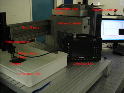
Source: Techno Inc.
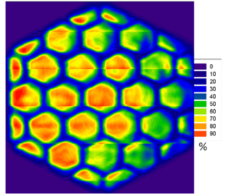
Figure 2: Phased array C-scan image of ceramic mirror material. Units are arbitrary percentage of ultrasound energy
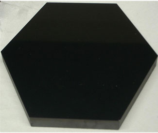
This shows the actual image of the top surface of Figure 2
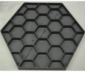
This shows the actual image of the bottom surface of Figure 2
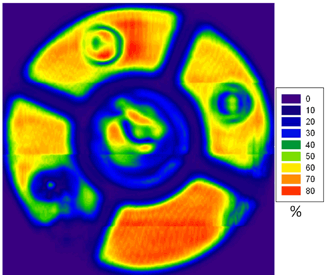
Figure 3: Phased array C-scan image of ceramic mirror material. Units are arbitrary percentage of ultrasound energy.
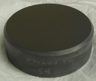
This shows the actual image of the top surface of Figure 3
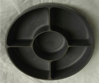
This shows the actual image of the bottom surface of Figure 3
Published April 6, 2012
A new approach can inspect a large number of parts in considerably less time than is required by conventional methods.
An ultrasonic phased array setup includes the integration of Techno and Olympus products.
Many materials such as armor-grade ceramics used in critical applications require 100% inspection. But conventional ultrasound inspection, a commonly used nondestructive method for evaluating ceramic integrity, may not be rapid enough for some commercial manufacturers. Researchers at Rutgers University have reduced the time required to inspect armor-grade tiles by mounting a phased array probe with 64 piezoelectric elements on a gantry machine. The Techno Gantry System LCT automatically moves the probe over the ceramic while providing positional information so the phased array instrument can measure material properties over large sample areas."This approach has proven to be at least 10 times faster than conventional ultrasonic inspection with a single element transducer," said Steve Bottiglieri, Graduate Student at Rutgers. "The precise motion of the gantry makes it possible to measure accurate property maps," added Andrew Portune, also a Rutgers Graduate Student. The Rutgers researchers worked closely with engineers from Techno to integrate Techno’s LC gantry with the OmniScan MX phased array module from Olympus.
Importance of nondestructive inspection
Dense ceramic materials are an attractive candidate for armor applications because of their low specific areal density and high hardness. Unfortunately, the uniformity of ceramics is not something which can be assumed. During the manufacturing process minor occurrences of anomalous defects can be found into the bulk of the material due to poor mixing of precursor powders, density gradients from compaction, thermal gradients within sintering furnaces or machining errors. During the manufacturing, these variables can lead to cracks, voids, or poor chemical phase mixing shown as agglomerations of sintering additives. It is also possible for internal cracks to form in the plates during shipping, handling and use of the plates. These flaws may significantly impact the performance of the tile in its application causing it to fail unexpectedly. These flaws are impossible to detect by manual inspection since they normally originate inside the material. This provides motivation for characterization each and every part.High frequency ultrasound has demonstrated the ability to detect flaws in ceramic plates. An ultrasound transducer is passed over the object being inspected. Ultrasonic waves travel by exerting an oscillating pressure on particles in a medium. In a solid medium where particles are closely bound, oscillation of one particle generates corresponding vibrations on adjacent particles, causing ultrasound propagation. The ultrasonic waves are captured by the transducer which receives the waves that are reflected by the object. The waves can be reflected by lamination layers in the material or by large anomalous flaws. Measuring the time at which reflections are received makes it possible to determine the location of the flaw within the ceramic material. Another option, not used in this application, is to receive the waves after they pass through the object.
The historic method of performing ultrasound inspection of ceramic tiles is to manually move a single-element probe over the material. It was difficult for an operator to ensure 100% sample coverage while focusing on the flaw detector display. Using this method as a mapping technique could highlight missed regions but was very slow. Modern methods reduce the amount of labor required by driving a single element ultrasonic transducer with a linear motion system. This method is effective in inspecting single or a few parts but can easily be overwhelmed by large batches of parts.
Phased arrays increase inspection speed
The speed of ultrasonic inspection can be increased through the use of phased array technology that combines a number of ultrasonic piezoelectric elements that operate simultaneously. Phased array systems pulse and receive from multiple elements of an array. These elements are pulsed in such a way as to cause multiple beam components to combine with each other and form a single wave front traveling in the desired direction. Similarly, the receiver function combines the input from multiple elements into a single signal.Because phased array technology permits electronic beam shaping and steering, it is possible to generate a vast number of different ultrasonic beam profiles from a single probe assembly. Beam steering can be dynamically programmed to create electronic scans. This enables software control of beam angle, focal distance, and beam spot size. These parameters can be dynamically controlled at each inspection point to optimize incident angle and signal-to-noise for each part geometry. Multiple-angle inspection can be performed with a single, small, multi-element probe and wedge, offering either single fixed angles or a scan through a range of angles. These capabilities provide greater flexibility for inspection of complex geometries in which part geometry limits access.
Integration of gantry increases inspection speed and reduces labor requirements
Rutgers has further increased the speed of ultrasonic inspection by integrating the Olympus Omniscan MX phased array ultrasonic system with the LC gantry from Techno. This approach reduces collection time by an order of magnitude when compared to the conventional single element setup. The gantry moves the inspection system over the samples automatically without requiring attention from an operator, so labor requirements are also dramatically reduced.Rutgers researchers wrote software using the MATLAB programming language to control the motion of the Techno gantry that accepts as input basic parameters of the parts being inspected. The program then generates a G-code toolpath file that guides the machine through the intricate series of motions required to produce the scaffold. "The task of creating the software to control the motion of the Techno gantry was greatly simplified by the Techno .dll package," Bottiglieri said. "The Omniscan MX unit requires encoder input to make collected sample information correspond to a spatial location," Portune said. "Techno was extremely helpful by modifying the linear motion controller to add a custom encoder output connector that interfaces with the phased array Omniscan unit."
The Techno Gantry System LCT is equipped with ball screws on all three axes with closed loop servo motor drives that provide an accuracy of +/-100 microns per 300 millimeters (mm) and a repeatability of +/- 100 microns. The Techno machine also provides a speed of 152 mm or 6 inches per second which is fast enough to achieve high inspection rates. The Gantry System LCT also features an XY travel of 30 inches by 24 inches. Each axis is provided with two double slide linear rails and four double bearing blocks.
The x-axis bearings and drive screw are mounted below the work surface to protect them from dust and debris. The x-axis is provided with an aluminum dust cover and plastic lips seals to provide protection against contaminants. Heavy cast aluminum side plates support the y-axis and provide increased stiffness for positioning and cutting applications. The machine comes complete with electronics, cabling, motors and software so the end user has a complete solution from a single source. This eliminates the cost and frustration of dealing with multiple vendors.
Validation of the phased array inspection system
The Rutgers researchers validated the new phased array inspection system by inspecting glass-ceramic tiles of varying compositions. Each tile was approximately 4" in length and width with a thickness between ½" and 1". For laminated samples, ultrasound characterization focused on locating delaminations or irregularities in the bonding between tiles. Non-laminated samples were evaluated for compositional uniformity through elastic property mapping and spatial measurement of the ultrasound attenuation coefficient. The lamination amplitude map revealed the location and severity of every delamination, making it an excellent indicator of variances in the bonding between tiles.A closer examination of lamination amplitude maps revealed additional information regarding the problem in the bonding layer between tiles. The best examples of this are seen in the lamination amplitude images for sample B and C. There appears to be two kinds of deviations from the mean peak amplitude seen in delaminated areas. In each area, higher amplitude areas can be seen adjacent to and surrounded by lower amplitude areas. The peak amplitude is directly related to the acoustic impedance mismatch between the two mediums found at the interface. Low peak amplitude means that the acoustic impedance mismatch was minimal. This could indicate a lack of bonding agent, or two glass ceramic tiles directly adjacent to one another. High peak amplitude indicates that the acoustic impedance mismatch was greater than the mean. This could indicate the presence of air or water in the delaminated area.
"The integration of the gantry machine and the phased array provides a major advancement in ultrasonic inspection of ceramic material," Bottiglieri concluded. "This new approach can inspect a large number of parts in considerably less time than is required by conventional methods. It also delivers excellent material property maps, making it possible to locate anomalous defects with a high degree of accuracy."
For more information contact: Techno, Inc. Linear Motion Systems, 2101 Jericho Turnpike, New Hyde Park, NY 11040. Phone: 516-328-3970 Fax: 516-358-2576 E-mail: TECHNO LINEAR MOTION SYSTEMS.


