Gantry Helps Test Unmanned Aerial Vehicles in Near-Earth Environment

Time to Read: 3m 0s
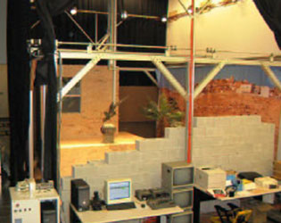
The Techno gantry is the heart of Drexel’s Systems Integrated Sensor Test Rig (SISTR). SISTR is a realistic testing environment for UAVs with the ability to recreate different environments and weather conditions.
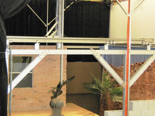
The Drexel made Blackhawk MAV undergoing testing on the gantry. Blackhawk’s sensor package is affixed to the gantry, and the gantry mimics the motion of the aircraft.
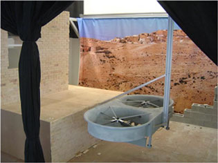
The Techno gantry is capable of lifting 35 lbs, allowing full scale UAVs to be attached to the end effector for collision avoidance tests.
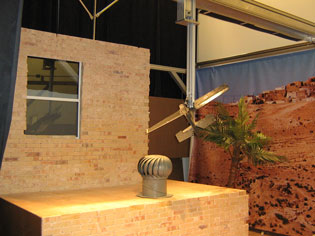
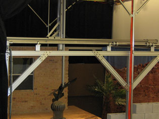
The Drexel made Blackhawk MAV undergoing testing on the gantry. Blackhawk’s sensor package is affixed to the gantry, and the gantry mimics the motion of the aircraft.
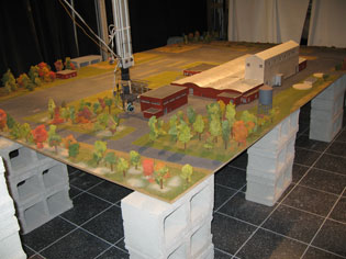
DASL is investigating the feasibility of testing UAV sensing and control algorithms in scaled down environments.
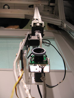
The UAV’s sensor suite is affixed to a pan/tilt/roll unit at the end of the gantry, allowing it to be “flown” through the mock environment.
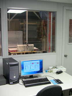
As the UAVs are virtually flown through the environment, real-time data is collected by the same software that will be used in flight.
DASL is a robotics lab located on the campus of Drexel University in the center of Philadelphia, Pennsylvania. The lab is run by Paul Oh, professor of Mechanical Engineering and director of Robotics for the National Science Foundation. DASL is the largest robotics lab on Drexel’s campus, and develops many different autonomous systems, from autonomous all-terrain vehicles to walking humanoid robots. It is well known for its work on UAVs, specifically on the sensing and control algorithms for flying UAVs in near-earth environments.
Having logged many hours flying autonomous planes and helicopters, the researchers noted that field tests come at a high cost in terms of both time and money. “The preparation for a field test and waiting for good weather to fly can take up to two weeks,” said Keith Sevcik, a researcher at DASL. “We live in fear of crashes. A crash can set you back thousands of dollars and months of development time. Most of our time is spent testing systems and building in safety measures to avoid crashes. The actual flights only last a couple of hours at most.”
Flight tests are the cornerstone of UAV research. The tests ensure that hardware and software systems work in concert, bridging the gap between lab development and real world application. But the cost of performing flights drives most researchers to focus on computer simulations, leaving the issues of implementation to someone else. There was no existing method to test computer code, flight control systems, sensors and other hardware without actually flying the UAV. To address this issue, the researchers at DASL envisioned the Systems Integrated Sensor Test Rig (SISTR).
SISTR is a hardware-in-the-loop test rig that can be used to characterize and design sensor suites, test control algorithms and emulate flight tests. The facility is designed to virtually fly the UAV sensors through a realistic environment. Sensor data feeds into a high-fidelity math model of the aircraft, which generates the aerial robot’s motion with a six-dof gantry. This allows the UAV to be rapidly developed in a controlled, measured setting.
The heart of the rig is a three-degree of freedom gantry from Techno, Inc., New Hyde Park, New York, that was custom built to provide the speeds and accelerations needed to simulate UAV flight. “The gantry has to have a large envelope of approximately 15 feet wide by 20 feet long by 10 feet high to enable the UAV to fly completely through the environment,” Sevcik said. “In addition, it needs very fine motion control and high levels of speed and acceleration to simulate UAVs flying through the space. Techno, Inc. provided a gantry table that meets all of these requirements.”
The gantry’s brushless DC motors position the gantry arm. The maximum payload is 35 pounds. The gantry has an x-axis travel of 17.72 feet, x-axis speed of 2 feet per second and x-axis acceleration of 2.95 feet per second squared. It has an y-axis travel of 13.84 feet, y-axis speed of 2 feet per second and y-axis acceleration of 3.69 feet per second squared. The gantry has a z-axis travel of 5.43 feet, z-axis speed of 2 feet per second and z-axis acceleration of 7.40 feet per second squared.
The remaining three degrees of freedom are provided by a Drexel-made pan/tilt/roll unit attached to the end of the gantry beam. The axes of rotation intersect at the center of the sensor, mimicking how most aircraft rotate at their center. This approach decouples rotations, allowing independent control over each axis. The pan/tilt/roll unit was constructed from Dynamixel AX-12 servos because of their small size, high torque, high speed and resolution.
The environment is represented by a scaled mockup of a near-earth environment. By scaling down the environment, a much larger area can be recreated inside the confined lab space. The environment was created at 1/87 scale so that HO railroad accessories can be used to dress up the model. The buildings and other manmade structures were created from foam core board. Natural features were roughly approximated using modeling materials.
A non-flying mockup of the UAV equipped with collision-avoidance sensors is attached to the gantry. The sensor data feeds into a high-fidelity math model of the real-world aircraft. The math model is used to control the motion of the gantry. The test rig also has a rain machine, dust machine, fog system, fans and lamps to reproduce rain, dust and fog. Twelve 750 watt lamps on the top of the rig are used to simulate day and night conditions. The environmental conditions in the facility can be adjusted in a controlled, repeatable manner.
The gantry is able to duplicate a large portion of the operating range of the UAV. All translational axes can be controlled within +/-0.5 cm. This scales up to a resolution of +/-0.43m, well within the +/-2m accuracy of off-the-shelf GPS systems. Sensors are mounted on the gantry and virtually flown through the environment. Real-time data is collected by the same software that will be used in flight. Control commands are fed into a mathematical model of the aircraft, which generates aircraft positions that are used to drive the gantry.
Evaluating UAV performance on test rig
The aircraft control software simulates the motion of the aircraft at full scale. The resulting position of the aircraft is then scaled and used to command the gantry. The test rig was used to investigate how the aircraft dynamics are affected by scaling. “Performance is greatly affected by the update rate,” Sevcik said. “The faster the communication between the software and the gantry, the more accurately that motion can be controlled. This directly affects the range of speeds that can be accurately reproduced. Faster speeds demand more position commands per second.”Aircraft were flown in the test rig at unscaled speeds ranging from 1 meter per second to 40 meters per second. The velocity was gradually varied to determine if there is an upper or lower bound on the boundaries that the test rig could reproduce. When the aircraft was moving at velocities greater than 30 meters per second the motion was erratic because the control was not updating fast enough. When the aircraft was moving slowly at around one meter per second, it was difficult to overcome static friction. Acceptable results were seen in the range between these extremes and the best results were obtained in the neighborhood of five meters per second.
The scaled tests were verified against baseline computer simulations. A standard UAV mission was selected in which the UAV uses a camera to guide itself to the center of a window while remaining a fixed distance from the building. Results showed that the tests at 1/87 scale were similar to simulations. After the scaled tests were validated, experiments were conducted to see how illumination and obscurants affect the camera.
“As illumination decreases, features around the windows of the building are lost,” Sevcik. “Instead, the white border around the top of the building is favored. Also, a shadow on the top of the building becomes more prominent as the lighting decreases, causing a feature to be detected on the roof. Generally, decreased illumination results in weaker and more difficult to track features. After testing the effect of lighting, fog was introduced. Fog tends to wash out the image but the same features are detected. However, these features are not as strong and more difficult to track. Though fog and weak illumination results in weaker features, vision still worked under these conditions.”
The test rig can be quickly outfitted with different aircraft models, control algorithms and sensors,” Sevcik concluded. “The Techno, Inc. gantry delivers the speed, acceleration and accuracy needed to simulate UAV flight. The environmental conditions in the rig can be adjusted in a controlled, repeatable manner. These results show scaling to be a promising avenue for designing UAV sensors, algorithms and missions. In particular it shows promise for developing algorithms that work under adverse conditions.


